Pumping Design Considerations for CO₂ Storage and Export Hubs, Ship Loading and Pipeline Transfer Applications
April 2026
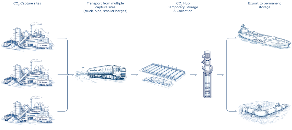
The emergence of CO₂ hubs constitutes a structural development in the architecture of carbon capture and storage infrastructure.
Rather than establishing direct connections between individual emitters and permanent storage reservoirs, hub-based configurations consolidate carbon dioxide from multiple sources, condition the medium, store it temporarily, and subsequently export it by ship or pipeline.
Such facilities function as critical infrastructure nodes within the CCS value chain. Their operational continuity directly affects upstream capture performance and downstream transport logistics. Consequently, equipment selection within these hubs must be guided by considerations of long-term reliability, safety integrity, and operational resilience.
Carbon dioxide must be regarded as a thermodynamically sensitive medium. Depending on prevailing pressure and temperature conditions, it may exist in liquid, gaseous, or solid phases. Under transient or upset scenarios, rapid phase transitions may occur. Pumping systems must therefore be designed with a clear understanding of phase behaviour, inlet stability, and mechanical robustness.
![]()
CO₂ Hub
CO₂ Hubs as Infrastructure Nodes
A CO₂ hub typically receives product from multiple capture plants that might be operating under differing pressure, temperature, and compositional conditions. The CO₂ is consolidated and stored in pressurised tanks prior to export by maritime transport or pipeline transfer to permanent storage sites.
Ship loading operations introduce variable flow demand and intermittent operating cycles. In contrast, pipeline export generally requires steady-state, continuous transfer over extended periods. In both operational modes, the pumping system must maintain stable inlet conditions while accommodating a dynamic operating envelope.
Given that many hubs will be located in industrial clusters or port environments, spatial constraints and civil design considerations influence overall layout. Tank geometry, foundation design, safety distances, and accessibility requirements interact with pump configuration choices. Pump selection thus becomes a structural design parameter within the broader infrastructure context.
The behaviour of carbon dioxide under storage and transport conditions differs fundamentally from that of many conventional industrial liquids. While CO₂ may be handled in liquid form within CO₂ hubs, its thermodynamic stability envelope is comparatively narrow.
As illustrated in Figure 1, typical hub storage conditions fall within the subcritical liquid region at pressures between approximately 7 and 30 bar. The corresponding temperatures are maintained close to the saturation temperature for the given system pressure. This ensures liquid conditions while operating within a limited thermodynamic margin to phase transition. Two characteristics distinguish CO₂ from fluids such as water.
First, the critical temperature of CO₂ is relatively low, at 31.1 °C. This means that many industrial CO₂ systems operate within a thermodynamic region that is inherently closer to the critical boundary than water-based systems, whose critical temperature is far above normal operating conditions. Consequently, pressure and temperature variations have a more pronounced effect on phase stability.
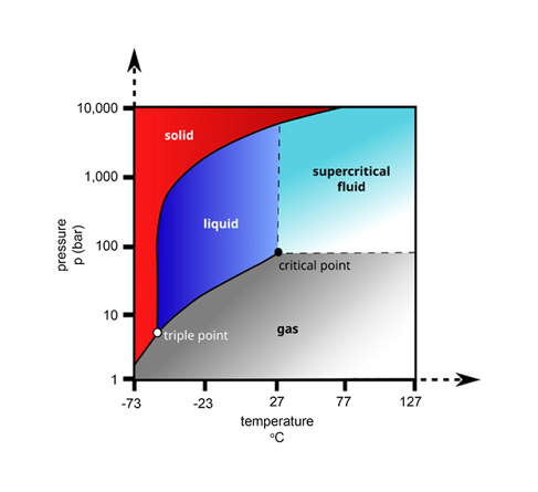
Figure 1: Pressure-temperature phase diagram for CO₂
Second, CO₂ exhibits a steep vapour pressure curve in the subcritical region. Small temperature increases can significantly raise vapour pressure, and modest pressure reductions may cross the saturation boundary. In practical terms, this implies that transient pressure losses at pump inlet may initiate flashing more readily than in systems handling higher-boiling-point liquids.
In addition, the triple point of CO₂, located at approximately 5.2 bar and –56.6 °C, lies within reach of certain refrigerated storage concepts. Under rapid depressurisation, pressure–temperature trajectories may approach the solid region, introducing the possibility of dry ice formation. Although such events are typically transient, their mechanical consequences can be significant.
For CO₂ hub applications, these thermodynamic characteristics underscore the importance of stable inlet control, conservative suction design, and pump configurations that minimize sensitivity to pressure fluctuations. Understanding the phase behaviour of the medium is therefore a prerequisite for sound mechanical and hydraulic design.


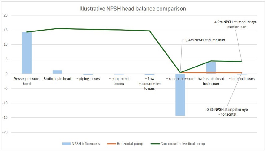
Figure 5 Illustrative NPSH head balance comparison for horizontal and suction-can configurations
The diagram shows relative head contributions expressed in meters of liquid CO₂. Under saturated storage conditions, vessel pressure head and vapour pressure head are of similar magnitude and therefore largely cancel in the available NPSH margin. As a result, the net suction head is primarily determined by static liquid head and suction losses.
For horizontal pump installations, the resulting NPSH at the pump inlet may be limited. In contrast, a suction-can configuration provides additional hydrostatic head at the impeller eye (ρ·g·h minus internal losses), resulting in a significantly higher effective NPSH margin and reduced sensitivity to flashing. Values shown are illustrative and not to scale.
Medium Behavior and Operational Sensitivity
Because CO₂ hub systems operate close to the saturation boundary, pressure losses at pump inlet have direct thermodynamic implications. A modest reduction in local pressure may shift the medium toward vapor formation, particularly in refrigerated storage configurations operating at lower system pressures.
In practical terms, this means that suction piping losses, transient flow disturbances, and thermal variations cannot be treated as purely hydraulic phenomena. They are thermodynamically coupled to phase stability. Pump configuration and inlet geometry therefore become decisive factors in maintaining stable liquid operation.
For long-life infrastructure, inlet stability must be secured structurally through controlled suction environments and conservative NPSH margins rather than through operational intervention alone.
Horizontal pumps are commonly applied in industrial services due to their simplicity and accessibility. Contemporary hydraulic designs may exhibit favourable NPSH characteristics under well-controlled conditions.
However, in CO₂ hub applications where NPSH availability may be inherently limited, horizontal configurations often depend on sufficient static head from storage tanks to ensure stable suction conditions. This typically necessitates elevated tank positioning or horizontal installation, increased liquid column above pump centreline, or recessed installations to augment available NPSH. While technically viable, such measures influence civil engineering scope, tank geometry, and overall site configuration.
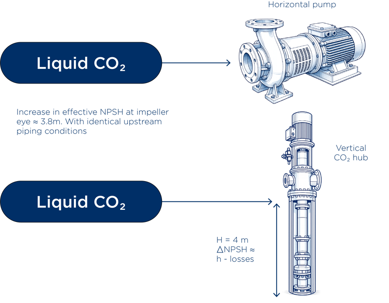
Vertically suspended, double casing diffuser pumps installed in suction cans follow a distinct architectural philosophy. The hydraulic assembly operates within a defined suction environment established by the can, reducing reliance on extended suction piping and high static tank head. Consequently, this configuration may provide enhanced flexibility in tank height, orientation, and civil layout, while maintaining predictable inlet behaviour.
Pump selection therefore extends beyond mechanical efficiency considerations and influences broader infrastructure design decisions.
Design Principles for Stable Pumping in CO₂ Hubs
Reliable CO₂ hub operation requires stable inlet conditions and mechanical robustness across varying operating states. Close hydraulic integration between storage volume and pump suction reduces exposure to pressure losses and transient disturbances.
In vertically suspended, double-casing diffuser pumps installed within suction cans, the outer casing provides structural containment while the inner diffuser assembly governs hydraulic performance. The suction can establish a controlled and repeatable inlet flow path toward the first-stage impeller, thereby reducing sensitivity to upstream piping
variations.
This configuration can reduce reliance on elevated tank designs to generate static suction head, enabling alternative tank geometries and site arrangements. Additionally, suction-can installations can support controlled tank stripping during maintenance, facilitating inspection and reducing downtime.
These design principles contribute to enhanced operational resilience and long-term infrastructure adaptability.
Implications for Ship Loading and Pipeline Export
In ship loading systems, variable flow demand and repeated start stop cycles require stable suction performance under transient conditions. Controlled inlet environments reduce the likelihood of flashing during operational adjustments.
Pipeline export systems emphasize continuous, steady state operation. Mechanical stiffness, diffuser stability, and minimized suction disturbances are essential for maintaining long-term reliability. Integration between storage tanks and pump configuration reduces system complexity and potential failure points.
![]()
Industry Experience and Technology Basis
DESMI has extensive operational experience with NDW and RSL deep well pump systems in LPG, LNG, and CO₂ service. These systems have been deployed in applications involving thermodynamically sensitive media and low-temperature liquid handling.
The suction-can-mounted configuration discussed in this paper builds on the same established hydraulic assemblies and mechanical design philosophy as the deep well systems. While the installation geometry differs, the diffuser hydraulics, shaft support principles, and vertical load management concepts remain consistent with field-proven designs.
By adapting proven deep well pump technology into a suction-can-mounted architecture suitable for land-based CO₂ hub layouts, it is possible to combine operational reference experience with an installation.
Conclusion
CO₂ hubs constitute long-term infrastructure assets within emerging carbon management systems. Their technical integrity depends on the stability of intermediate handling systems operating near thermodynamic phase boundaries.
Pump configuration decisions influence not only hydraulic performance but also tank design, civil engineering scope, operability, and lifecycle risk. Stability-oriented design philosophies that prioritize inlet control and mechanical robustness contribute to resilient and adaptable hub infrastructure


